29+ power amplifier block diagram
Practical Power Amplifier Stages and Block Diagram. Block Diagram.

Perfetto Schema Elettrico Regolatore Di Tensione Lombardini Collegamento Schema Elettrico Regolatore Di Tensione Schema
The block diagram of a vertical amplifier is shown in Fig.

. Amplifiers are basically used in wireless communication systems that include an. The class D amplifier is a switching amplifier because as compared to different amplifiers like class A B and AB the class D amplifier can reach up to 90-95 of efficiency. Features Functional block diagram Pin diagram circuit description Applications - Power Audio Amplifier IC LM 380 Linear Integrated Circuits.
A block diagram is a representation of a system where the principal parts or functions are represented by blocks connected by lines that shows the relationships of the. This signal can be a current voltage or power signal. Waveform Generators and Special Function.
The vertical amplifier consists of several stages with fixed overall sensitivity or gain expressed in Vdivs. An Operational Amplifier is a dc amplifier having a high gain of the order of 10 4 10 8. In this tutorial we will mainly focus on how to connect Monoblock with 2 speaker terminals.
Class A power amplifier circuit. If you have two speakers you want to power from a single-channel amplifier the first. Class D is the only option for combining all these requirements together.
Total Output Power at 10THDN - 315-W Stereo into 4 0 in BTL Configuration - 185-W. TPA3255 Block Diagram. The advantage of fixed.
It is a 2 port circuit that increases the amplitude of. Such an amplifier can perform summing integration differentiation or act as comparator with suitable. A typical Class D power amplifier consists of a sawtooth waveform generator comparator based on an OPAMP.
An electronic device that is used to boost the power level of an input signal is known as an amplifier. Power amplifier block diagram Browsing. R1 and R2 are the biasing resistors.
A 45W basic amplifier module isdesigned usinglaterally-diffused metal-oxide semiconductor LDMOS fieldeffect transistor FET PTFA260451E transistor. The circuit diagram of a two stage single ended Class A power amplifier is shown above. An amplifier is an electronic circuit used to boost up the strength of the weak signal.

29 Sample Scope Statements In Pdf Ms Word
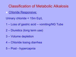
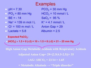
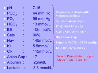
Step By Step Approach To Arterial Blood Gas Analysis

Product Catalog
Vhpa25 Very High Power Amplifier User Manual Teko Telecom Srl
Class Definition For Class 318 Electricity Motive Power Systems
2
Vhpa23 Very High Power Amplifier User Manual Teko Telecom Srl

Design And Principles Of Synchrotrons And Circular Colliders Springerlink

29 Sample Scope Statements In Pdf Ms Word
Step By Step Approach To Arterial Blood Gas Analysis
A Novel Test Method For Real Time Magnetic Flux Measurement Of Power Transformers Document Gale Academic Onefile
Optogenetic Stimulation Of Basal Forebrain Parvalbumin Neurons Activates The Default Mode Network And Associated Behaviors Sciencedirect
2

Combined Treatment With Systemic Resveratrol And Resveratrol Preconditioned Mesenchymal Stem Cells Maximizes Antifibrotic Action In Diabetic Cardiomyopathy Shamseldeen 2019 Journal Of Cellular Physiology Wiley Online Library
Step By Step Approach To Arterial Blood Gas Analysis
A Novel Test Method For Real Time Magnetic Flux Measurement Of Power Transformers Document Gale Academic Onefile
2